How to Calibrate a Pneumatic Inlet Valve
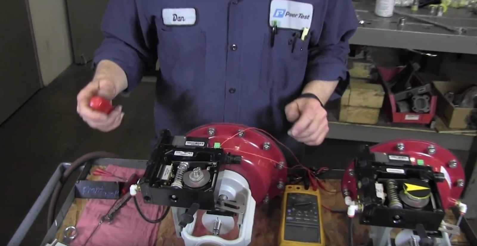
This Tech Tip will cover the calibration procedures on a pneumatic inlet valve, which can be found on Power Test’s Water Brake Chassis Dyno and some Water Brake Engine Dynamometer applications.
The first step is to loosen the set screw in the camlock nut. Next you need to loosen the camlock nut itself. When you do, the cam will rotate freely and the follower will fall into the valley of the cam. We want to verify the follower will roll up the 30 degree side of the cam as the valve opens. To do this remove the cam and flip as necessary to ensure it rolls up the 30 degree side. Slide a screwdriver underneath the feedback arm at the bottom of the cam to take the pressure off the cam. Rotate the cam slightly and then tighten the assembly with the camlock nut. You want a small gap to exist between the follower and the valley of the cam. Once you have it set, tighten the camlock nut and then re-tighten the set screw that we loosened earlier. To ensure everything is tight. Use a small screwdriver to lift up on the feedback arm and snap it a little bit. If everything is tight, the cam will stay in position and won’t fall back into the alley. The first red indicator line on the cam should point to the center of the follower. If the follower turns to the valley, or sits higher than the first red indicator line of the cam repeat these steps until you have the follower in the correct position.
The next step is to apply a 30 PSI air supply to the s-port on the side of the valve. We recommend running your air supply through a pressure regulator before the valve. Set the regulator to 0 and then slowly increase the pressure to 30 PSI so you don’t accidentally overpressure the valve. We also want to create an input signal, or command signal, into the valve. The valve runs on a 4 milliamp to 20 milliamp command signal and you can use a multi-meter or you can use your Commander PC and the CD controller software to use as a signal source.
To check valve operation, step up the valve in increments until you are at 100% valve or a 20 milliamp signal. Verify the followers at the top of the 30 degree cam load at a 20 milliamp signal. Also check the zero or seated position of the valve. With a 5 milliamp signal the valve arm should just start to move off its seat. If necessary adjust the zero set screw at the bottom of the valve to adjust the seated position of the valve. To complete the calibration procedures will all adjustments completed, using the CD controller or your 4 to 20 milliamp signal source, step the valve up once again in increments to verify operation.


