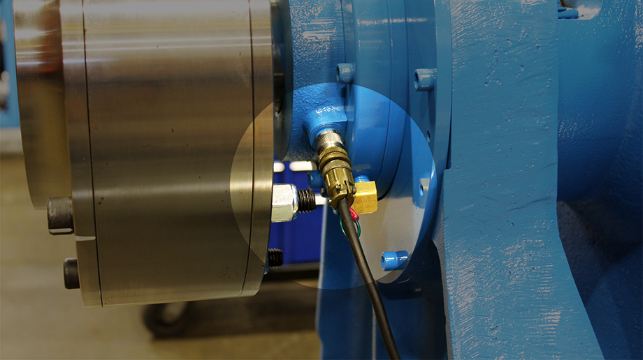
How to Troubleshoot Speed Sensors
The following will confirm speed sensor wiring is damaged. The sensor cable connector will have two or three female plugs labeled “A” thru “C”. Number of plugs is dependent on the type of speed sensor, engine dynamometers typically use a two wire speed sensor, while other Power Test/AIDCO products normally use a three wire speed sensor.
Disclaimer: Not all possible Speed Sensor damage can be confirmed, even if the following checks confirm sensor wiring is good, it still may require replacement.
1.) Check Sensor Connection
Locate the speed sensor connection point on the WorkStation circuit board or WAGO module within PowerNet controller enclosure. Both the WS circuit board or WAGO module will have an LED that blinks with speed signal. Manually rotate dyno shaft or chassis dyno roll and look to see if LED blinks.
If LED does NOT blink, problem is in wiring from the LED connection point to the speed sensor or a damaged speed sensor. If it blinks, most likely issue is software related, which is not covered by this tech tip.
2.) Check Gap
If able, ensure the gap between the Speed Sensor and Timing Gear is within tolerance.
The speed sensor should be secure in its mounting with a clearance of .015 inch to .025 inch between the sensor and timing gear.
3.) Resistance Measurement (two wire plug only)
Remove speed sensor connector plug at Work Station or controller enclosure and then measure resistance across pins “A” to “B”.
The measured resistance should be approximately 1,000 ohms on p/n: 11026. If you read an open loop, check the speed sensor, connector, and wiring for breaks.
4.) Check Power (three wire plug only)
Remove speed sensor connector plug/wiring from Work Station or controller enclosure and check for 12VDC or 24VDC (sensor dependent) at connection point. Use electrical schematics to determine test voltage, power wire (typically red wire) and ground wire (typically black wire).
The measured voltage should be 12VDC or 24VDC (sensor dependent) between power and ground wires. If no voltage is read, controller is not powering sensor, which is not covered by this tech tip.
5.) Check Wiring (three wire plug only)
Remove speed sensor connector plug/wiring from Work Station or controller enclosure and plug from the speed sensor itself. Test continuity of each of the three wires from plug/wiring end to plug end.
Continuity should be detected on each of the three wires. If you read an open loop, check wiring for breaks.


