


How to Install a Driveshaft to Your Dynamometer
When installing a driveshaft between a dynamometer and an engine (or transmission), there are a few factors to consider. Some of these are orientation, alignment, and slip. Any of these factors have the potential to cause premature driveshaft failures if they are not set properly.
Orientation
The hollow tube with the male spline should be the driving side. In an engine dyno application, the tube side would be connected to the engine. In a transmission dyno application where the drive shaft is installed between the test stand and the transmission, the tube side would be connected to the test stand. In a transmission dyno application where the drive shaft is installed between the transmission and the output load unit, the tube side would be connected to the transmission.
Alignment
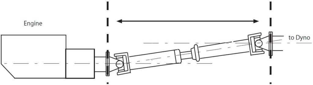
The faces of the flanges at each end of the driveshaft must be parallel.
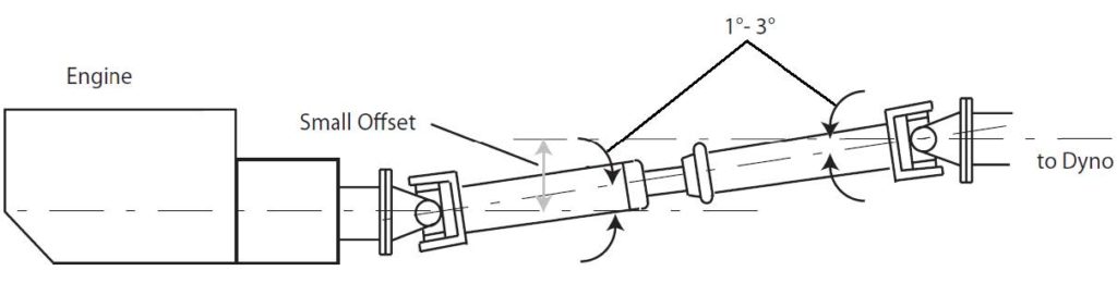
However the flanges of the driveshaft should have a small offset (up/down or left/right) so that they do not have the same centerline. This will create an angle in the u-joints of approximately 1° to 3°. This is called parallel misalignment. The dynamometer sub-bases and engine carts manufactured by Power Test Inc. will have a slightly different centerline height which will automatically create this parallel misalignment.
Slip
A driveshaft should not be operated in the fully collapsed position in order to prevent binding. It is common for the driveshaft to be extended one inch from the fully collapsed position during operation.